| VME trigger requirements |  |
Production readout can take trigers via a CAEN V262 VME I/O module. This module must have its base address switches all set to 4 (base address of 0x444400). The VME trigger is the default trigger. To use a CAMAC trigger (possible if you have a CES CBD8210 CAMAC Branch highway driver) you must start readout with the -camac-trigger switch.
If you have selected a VME Trigger you must set up two external latch channels. (NIM gate and delay generators in latch mode work just fine). Since the inputs on the CAENV262 don't latch the first channel will be used to maintain the gate signal true until the computer responds to it. The second will indicate when the computer is busy. The CAENV262 inputs and outputs are used as shown below:
| Plug name | Signal meaning |
| IN 0 | Computer Master Gate (live) |
| Shp 0 | Computer going software busy |
| Shp 1 | Computer going ready |
| Shp 2 | Trigger acknowledge |
| Shp 3 | Module clears |
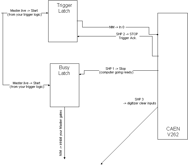
These signals should be hooked to the experimental electronics as shown in the figure below:

The Master.live trigger comes in from your experiment trigger logic and, in the trigger latch produces a trigger that is held asserted as long as is required for the computer to react to it. When the computer reacts to the trigger, it pulses SHP 2 (Trigger acknowledge), de-asserting the computer trigger input.
The Master.live trigger also sets the busy latch which inhibits further gates from your experimental electronics. When the computer has finished reading an event it pulses SHP 3 (Module clears) which you can fan out and use to clear digitization modules that have external clear inputs. Finally, it pulses SHP 1 (Computer going ready) which clears the busy latch, enabling the electronics to gate the next event into the computer.
| VME trigger requirements |  |