| CAMAC trigger requirements |  |
If you have selected a CAMAC trigger, you must use a single external latch to inhibit gates to the system while the computer is busy. The computer part of the trigger system consists of two modules:
If available, you may use channel 1 of an LRS2323A CAMAC programmable gate generator in slot 21/22 instead of an external latch. If you do so, you need not externally stop this module. If not used, these two slots must be kept empty as the computer software will send function codes to this slot as if the module were plugged in. The remainder of this section assumes that you are using an external (e.g. LRS 222 NIM GDG) latch rather than a CAMAC latch.
The signal specifications are described in the table below:
| Signal | Meaning |
| CBD8210 INT2 | Computer trigger. |
| BiRa 3251 out1-8 | Module clears |
| BiRa 3251 out 9 | Software busy begins |
| BiRa 3251 out 10 | Going ready |
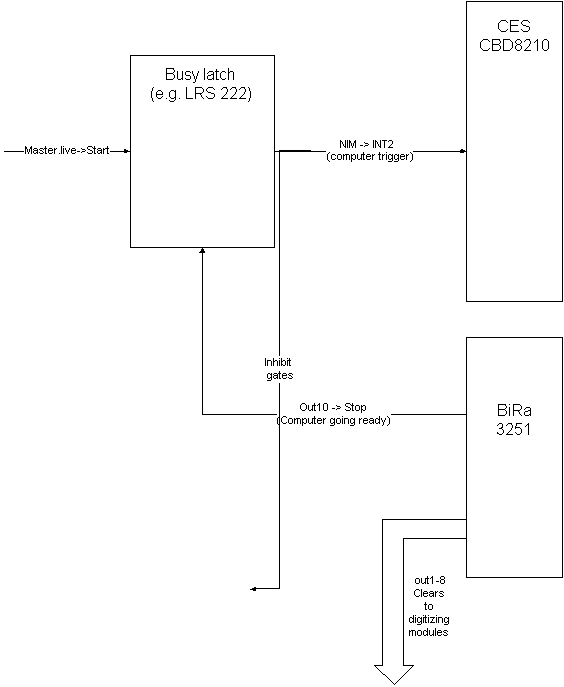
Given this set of signal specifications, the suggested CAMAC trigger logic is shown in the figure below.

It is not really necessary for the master gate to be latched by the the Busy latch, before triggering the computer as the CES CBD8210 latches INT2 until reset by the computer we suggest doing this, however becuase in this way, if you have an intermittent cable, you won't hang the system; once a correct cable is plugged in, the trigger will be sensed.
The figure shows the busy latch set by the master.live. The NIM output indicates that the trigger electronics should inhibit further gates. The NIMOUT Out 1-8 are pulsed after readout is complete and may be directly plugged in to digitizer clear inputs. The NIMOUT Out 10 (Going ready) clears the NIM latch indicating that the computer is ready for another gate.
| CAMAC trigger requirements |  |