Multi-Crate System Setup Guide
Table of Contents
- Date
- 4/17/24
Introduction
- A single PXI crate can accommodate up to 208 channels. Some experiments using DDAS require more channels and therefore more than one crate of electronics. Setting up a multi-crate system is similar in many ways to setting up a single-crate system. There are however a few extra steps that are important to get right for the system to operate correctly. In this tutorial, we will cover:
- The components of a multi-crate system,
- How to set up DDAS electronics for a multi-crate experiment,
- How to understand the data in the data stream,
- How to develop a tailored SpecTcl to analyze it.
- If you are new to using DDAS and have not setup a system before, it is highly recommended that you begin with the Single-Crate System Setup Guide.
- Attention
- This multi-crate system setup guide is specific to DDAS systems running NSCLDAQ 12 and later, which has a handful of major features which were not part of previous releases:
- The module data readout and sorting processes are decoupled. As a consequence, readout program data sources must be configured in a slightly different manner.
- The DDAS codebase has been refactored into NSCLDAQ, there is no need to source a DDAS setup script in e.g., /usr/opt/ddas.
- External clock readout has been absorbed into the main readout program. There is no longer a separate version of the DDAS readout for this purpose.
- As of XIA API major version 3, settings files are saved in JSON format. Files with names like crate_1.json are the JSON version of the binary settings files generally named crate_1.set for previous XIA API releases. Note that there is no strict enforcement of file extensions: a JSON settings file can be saved with a .set extension. The .json extension is used here to remind the reader familiar with older versions of the NSCLDAQ that these settings files are not the binary settings files they are familiar with. Further it should be noted that JSON settings file are not back-compatible with older NSCLDAQ versions using XIA API 2, and that there is no supported way to convert a JSON settings file into binary format.
Components of a DDAS System
- DDAS data acquisition systems and online analysis rely on several hardware and software components. Most of these are covered in the Single-Crate System Setup Guide. Of course, for a multi-crate system, two or more PXI crates, data-collection computers, and Pixie digitizer cards are required. In addition, you will need:
- One Pixie trigger distribution board for each crate in the system.
- One Category 5 or Category 6 (henceforth "Cat 5" or "Cat 6") cable per crate to distribute the shared clock. There are standard 2-meter Cat 6 cables available from the SDAQ group. For distributed systems where the crates are located far apart, longer cables can be used, though it is important that all cables are the same length to minimize clock phase differences across the crates.
- The architecture of a multi-crate system is quite similar to that of a single-crate system. The two crates share a common clock, distributed by the clock master through the PXI backplane to all other modules in the system (more on that later):
A schematic DDAS hardware configuration for a multi-crate system. Two PXI crates with single-board computers (SBC) used as the data-collection computers, each containing a single Pixie module, are connected via the FRIB DAQ network to an analysis computer.
- The dataflow is similar as well. Each crate acts as an individual data source with its own readout and sorting pipeline. The output of the sorters for each crate are merged into a single datastream at the event-building stage:
Data flow through a multi-crate DDAS system running NSCLDAQ 12. Note the separation of module data readout and sorting, which were previously part of a single process. This configuration enables much higher data readout speeds. Multiple data data sources are combined at the event-building stage into a single datastream.
Getting Started
- For brevity's sake, only things which are unique to multi-crate systems are covered here. For a more detailed explanation of the software and configuration files needed by DDAS please refer to the Single-Crate System Setup Guide.
Loading the PLX Kernel Driver
- Users are no longer required to load the PLX kernel module by hand on each data-readout computer installed as part of your DDAS system. The kernel module is loaded automatically on system startup.
Configuration Files Needed by NSCL DDAS
- As a reminder, a general DDAS directory tree looks like:
home-directory
      |
      +--- readout
              |
              +--- crate_1  (configuration for crate 1)
              +--- crate_2  (configuration for crate 2, if needed)
              ...
              +--- crate_n  (configuration for crate n, if needed)
- We can expand the full directory tree for a multi-crate system running two crates:
home-directory
     |
     +-- readout
            |
            +--- crate_1
                    |
                    +--- cfgPixie16.txt
                    +--- modevtlen.txt
                    +--- crate_1.json
            +--- crate_2
                    |
                    +--- cfgPixie16.txt
                    +--- modevtlen.txt
+--- crate_2.json- The example crate_1 directory located at
$DAQSHARE/ddasreadout/crate_1 containing the necessary configuration files can be copied for each crate in your system. It is recommended that you edit the names of the settings files within each directory to reflect the crate of modules using those settings. The configuration files should be edited in the usual way to reflect your setup, again refer to the Single-Crate System Setup Guide.
Setting Up a Multi-Crate System
- This part of the guide will discuss in detail how to setup a multi-crate DDAS system with one or more XIA digitizer cards in each crate. To keep things simple we will assume a two-crate system using a common clock with a clock master and clock receiver. Any additional crates should be configured as clock receiver crates. To get started you must:
- Ensure that there is an SBC or fiber interface in slot 1 of each PXI crate (the most common case). If a fiber interface is used, the fiber must be connected to the interface card and a PCI bridge card on the data-collection computer. The data-collection computers must be connected to the DAQ network.
- Install a Pixie module configured as a system clock master in slot 2 of your clock master crate.
- Install a Pixie module configured as a chassis clock master in slot 2 of your clock receiver crate.
- Ensure all other modules in slots 3-14 of the clock master and clock receiver crates are configured to read the clock from the PXI backplane.
- Setup the clock distribution between crates.
- Attach signals to the digitizer inputs.
- Configure your DSP settings.
- Attention
- At FRIB, the NSCLDAQ software is run from within a container. To run the NSCLDAQ software discussed in this tutorial, you may need to edit your container startup script or script(s) you use to launch NSCLDAQ programs following the instructions provided under "Containerized NSCLDAQ" found on the SDAQ homepage. For systems running Singularity, you must define the environment variable
SING_IMAGEto be the full image path and store the bindings you are using in the~/.singularity_bindpointsfile.
- Step 1 is relatively straightforward and need not be discussed further. Steps 2-5 are more complex and will be covered in detail in the subsequent sections. Steps 6 and 7 are essentially the same as in single-crate systems, so only the differences will be discussed.
- Warning
- SBCs, fiber cards and modules are NOT hot-swappable. DO NOT connect or disconnect SBCs, fiber cards or modules from the crate while it is powered on. Before installing or replacing any DDAS hardware, ensure that the crate is powered off.
Clock Distribution Settings for a Multi-Crate System
- When using several DDAS crates it is important to synchronize the digitizer clocks between them. This is done by setting the jumper block JP01 appropriately for every card in the system. The jumper block is a set of pins located on the board near the backplane connectors, shown on the figure below in the red box. Configure the connections between these pins with jumpers.
- The standard way to distribute clocks between Pixie modules at FRIB is to use the PXI backplane. In multi-crate systems, one of the Pixie modules can provide a global clock to the rest of the modules across multiple crates. This module or crate are referred to as the "system master module" or "system master crate," respectively ("clock master" or "director" are frequent synonyms). There is only one system master module. All other modules/crates are referred to as "chassis" (or, occasionally, "clock receiver" or "clock recipient") modules or crates. There are as many chassis master modules as there are additional crates.
- The module installed in slot 2 of the system master crate is configured to be the system master module and provides the global clock. The module installed in slot 2 of a chassis crate is called a "chassis master module" and is responsible for receiving the global clock and redistributing it to other modules installed in the chassis crate. All other modules read the clock from the PXI backplane.
[Left] A Pixie-16 board with the location of the JP01 jumper block shown in the red box. [Right] Schematic of the jumper settings for distributing the clock across the PXI backplane for a multi-crate system. Top: PXI clock system master jumper settings (slot 2 of system master crate). Middle: PXI clock chassis master jumper settings (slot 2 of chassis master crate) Bottom: PXI clock recipient jumper settings (slots 3-14 of all crates). Figures reprinted from 'Pixie-16 User Manual', Version 3.06, XIA LLC.
- It is very important to get these jumper settings correct. If the modules are configured incorrectly, the host computer that is reading out the data will likely end up in an unrecoverable error state and freeze. If this happens, do not panic, nothing is broken. You must turn off the crate and computer, correct the jumper settings and reboot the computer.
The Clock/Trigger Distribution Board
- In order to send the clock between the crates, a Pixie trigger distribution board must be plugged into the back of each chassis in the system, into the rightmost slot in the rear of the crate so that it is immediately behind the module installed in slot 2. The trigger board is an essential piece of hardware used to connect the system together. It distributes the clock from the multi-crate system master module and passes it to the chassis master in every other crate. Those chassis masters then are responsible for distributing the clock to the other modules in the system by putting it on the PXI backplane. The user must connect these boards together.
- There are three groups of connectors on the trigger board. The top-most group consists of four outputs 0-3, in order from top to bottom. The middle of group consists of outputs 4-7, once again in order from top to bottom. The bottom group consists of two inputs B and A in order from top to bottom. A photo of a trigger distribution board is shown below.
The Pixie-16 trigger distribution board. The bottom of the board is on the left side of this photo
- There are a number of jumpers on the trigger board. We do not typically deviate from the standard master configuration. Make sure that the following pins are set for the jumpers on each of the trigger boards in your system:
| Jumper | Connections |
|---|---|
| JP1 | P16 |
| JP20 | 2-3, 6-7 |
| JP40 | 2-3, 6-7 |
| JP60 | 1-2, 7-8 |
| JP21 | normal |
| JP41 | normal |
| JP61 | reverse |
| JP100 | Connect to J4 |
| JP101 | Connect to J4 |
| JP102 | Connect to J4 |
| JP103 | Connect to J4 |
| JP104 | Connect to J4 |
| JP105 | Connect to J4 |
- The trigger board in the system master crate, immediately behind the system master module, will need to connect one of the outputs to its own input A. A second output should then be connected to input A of the chassis crate. The wiring scheme looks like this:
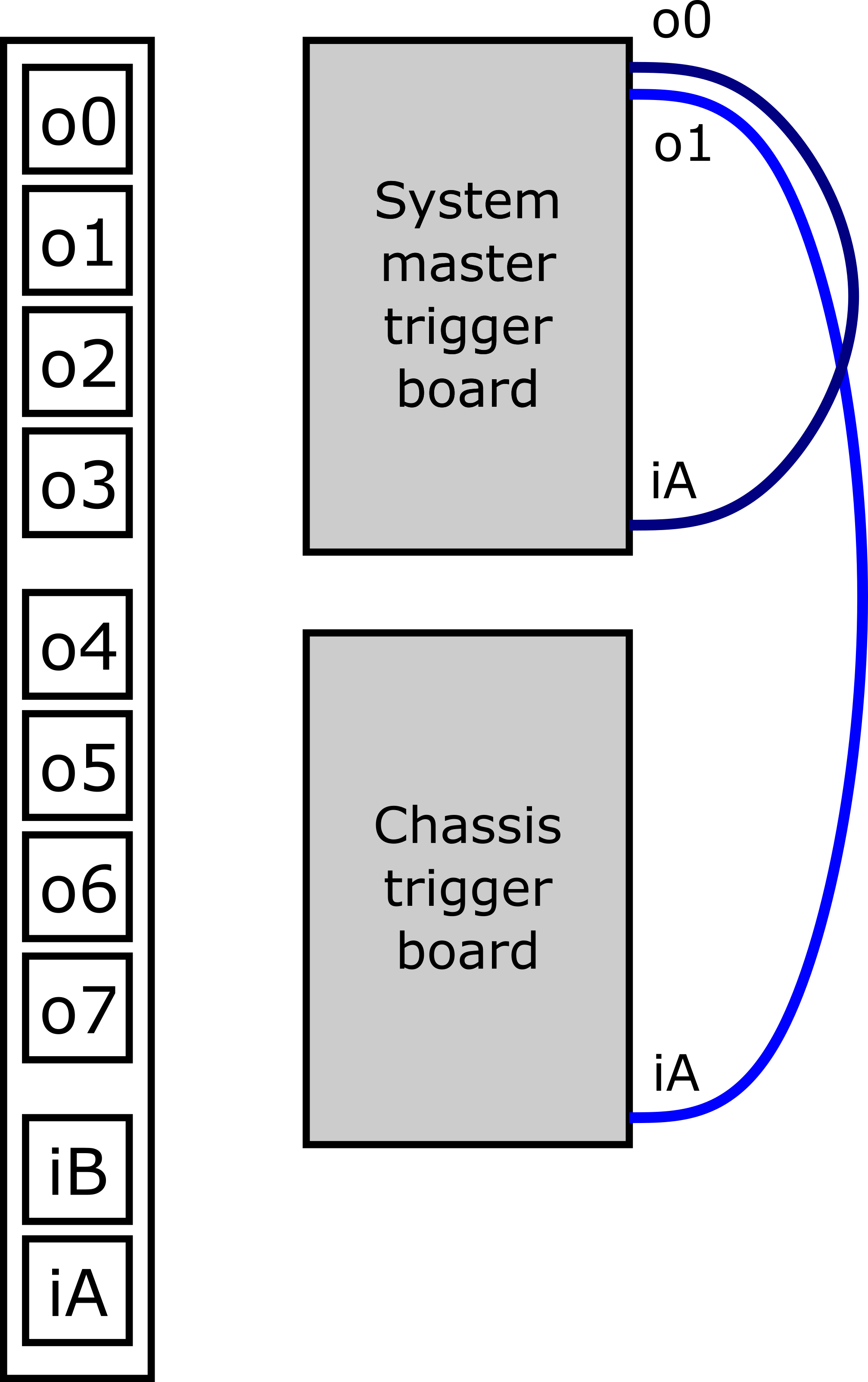
[Left] The front panel of a Pixie trigger distribution board with the outputs (o1, o2, ...) and inputs (iA, iB) labeled. [Right] Wiring scheme for a two-crate system. The 2-meter Cat 6 cables used to connect the trigger boards are shown in blue (not to scale).
- Note
- On the above figure, the Cat 6 cables connecting the trigger boards are not shown to scale. The two cables must be the same length.
Configuring an Input Signal
A test signal from a pulser is used for this tutorial. Setup the pulser to output pulses that rise quickly but have an approximately 50 μs decay time. The test pulse should be negative (-) polarity, have an input voltage of less than 1 V and a frequency less than 5 kHz. Connect the test signal to channel 0 of the digitizer.
Example Configuration Files
- The setup described in this tutorial contains two crates with one digitizer in each. Crate 1 is the system master crate and crate 2 is the chassis. In our crate_1 directory under the top-level readout directory, we have DSP settings stored in crate_1.json. The cfgPixie16.txt file for the first crate looks like:
1  # crateID
1  # number of modules
2  # slot for mod 0
/user/0400x/ddas_xiatest/readout/crate_1/crate_1.json
- Similarly, for crate 2:
2  # crateID
1  # number of modules
2  # slot for mod 0
/user/0400x/ddas_xiatest/readout/crate_2/crate_2.json
- Note that the
crateIDis different in crate 2's cfgPixie16.txt file. This ID value is used by the ScalerDisplay program to identify each crate in the system. The ID value should be different for each crate in your system to ensure that scaler data are displayed correctly.
Configuring DSP Settings Using QtScope
- For brevity, refer to Configuring DSP Settings Using QtScope for information on configuring single-channel DSP settings. Note that you must run QtScope on each data collection computer from the crate directory containing the settings for the crate in which that data collection computer is installed.
- In addition to the channel DSP settings, the module DSP parameters must be set to enable the distribution of the clock and synchronization signals. The clock and synchronization signals are controlled by the Module Control Register B or ModCSRB parameter. ModCSRB is a 32-bit parameter where each bit controls an operation mode of the digitizer module. Some pre-configured ModCSRB settings are available in QtScope that handle the majority of use cases. In the QtScope GUI, click the [Module DSP] button on the system toolbar which will bring up the following window:
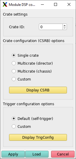
The module DSP popup window displayed when clicking the [Module DSP] button.
- Crate configurations are selected by clicking on the radio button to the left of the text describing the configuration type. For the system master crate, use the Multicrate (director) crate configuration; for all other crates, use the Multicrate (chassis) configuration. A customizeable crate configuration is also provided for more complex setups. You can display the actual ModCSRB settings by clicking the yellow [Display CSRB] button. Each crate in the system must have a unique crate ID.
Running ddasReadout Using the ReadoutGUI
- This section describes how to configure data sources, setup an event builder and run the readout driver for DDAS in a "production-like" mode using the ReadoutGUI. For users familiar with previous versions of FRIBDAQ software, the data-source configuration is done slightly differently in FRIBDAQ 12, reflecting the fact that the module readout and timestamp ordering processes are separated. The
ddasReadoutprogram allows us to run the module readout and timestamp sorting as if it were a single process. This section has a good deal of overlap with Running ddasReadout Using the ReadoutGUI for a single-crate system and only important differences will be highlighted here.
Setting up SSH keys for Password-Less Login
- Refer to Setting up SSH keys for Password-Less Login in the single-crate tutorial for instructions on configuring password-less login over SSH.
Stage Areas and Recording Data
- Refer to Stage Areas and Recording Data in the single-crate tutorial for instructions on how to setup a stagearea.
Setting Up the Data Sources
- Refer to Setting Up the Data Sources in the single-crate tutorial for instructions on how to set up an SSHPipe data source in the ReadoutGUI. In a multi-crate system, one data source is needed for each crate:
- The data source options for crate 1:
| Field name | Contents |
|---|---|
| Host name: | Name of the host on which the readout will run. I used: spdaq05. |
| Readout program: | The readout driver program from your $DAQBIN. Enter the full path or navigate to that directory using the Browse button.I used: /usr/opt/daq/12.1-xiaapi4/bin/ddasReadout. |
| Working directory | Set to the directory containing the DDAS configuration files. Un-check the "Same as Readout" box and either enter the full path or navigate to that directory using the Browse button.I used: /usr/0400x/ddas_xiatest/readout/crate_1 |
| Command line options | Options for running the readout driver code. I used: -readouthost spdaq05 -readoutring 0400x_raw_1 -sorthost spdaq05 -sortring 0400x_sort_1 -cratedir /user/0400x/ddas_xiatest/readout/crate_1 |
- And similarly for crate 2:
| Field name | Contents |
|---|---|
| Host name: | Name of the host on which the readout will run. I used: spdaq10. |
| Readout program: | The readout driver program from your $DAQBIN. Enter the full path or navigate to that directory using the Browse button.I used: /usr/opt/daq/12.1-xiaapi4/bin/ddasReadout. |
| Working directory | Set to the directory containing the DDAS configuration files. Un-check the "Same as Readout" box and either enter the full path or navigate to that directory using the Browse button.I used: /usr/0400x/ddas_xiatest/readout/crate_2 |
| Command line options | Options for running the readout driver code. I used: -readouthost spdaq10 -readoutring 0400x_raw_2 -sorthost spdaq10 -sortring 0400x_sort_2 -cratedir /user/0400x/ddas_xiatest/readout/crate_2 |
Setting Up the Event Builder
- The
ReadoutCallouts.tclscript used to start the event builder is very similar to what is presented in the single-crate tutorial with again, the key difference being the addition of another data source fed into the event builder:
package require evbcallouts

::EVBC::useEventBuilder

proc OnStart {} {
    ::EVBC::initialize -restart true -glombuild true -glomdt 100 -destring 0400x_evb
}

::EVBC::registerRingSource tcp://spdaq05/0400x_sort_1 "" 0 Crate_1_DDAS 1 1 5 0
::EVBC::registerRingSource tcp://spdaq10/0400x_sort_2 "" 1 Crate_2_DDAS 1 1 5 0
- The data in the event-built ring will look similar to the single-crate data except that fragments from both crates can be built into a single event if they satisfy the build window conditions.
Conclusions
- This concludes the multi-crate setup tutorial. You should now have a good understanding of how to perform the basic steps necessary to configure a multi-crate DDAS system to take data. The modules have many features which are not discussed in detail in this section, including a digital CFD for precision timing, the ability to run complex coincidence triggers, or take additional data such as QDC sums or, more commonly, ADC trace data. Refer to the QtScope Manual for more information.